Sound reactive LED matrix
Terms used in this document
BOM: Bill Of Materials
PCB: Printed Circuit Board. They are made of a composite material which is primarly fibreglass board (specifically FR4).
LED: Light Emitting Diode. It is a light.
IC: Intigrated Circuit.
USB-C: Universal Serial Bus Type C (the charger used on most modern laptops and phones).
Traces: In the context of PCB design, these are the copper wires on top and bottom of the board which actually make it a circuit.
Footprints: In the context of PCB design, these are the copper connection points that are designed specifically for each part so they can be soldered to the PCB.
Schematic: A diagram showing what pins on what components need to be connected together. It does not show how to connect them physically, that is what traces are for.
Why this project?
From the beginning, I knew I wanted to do something a bit different, and not just focus on traditional art. I also knew that I wanted something that I could enjoy or use after I finished creating it. Most importantly, I also wanted to learn something new, or at least get more experence with something I am already familliar with. My train of thought went something like this:
- A drawing robot would be cool
- The BOM of a drawing robot is very large, meaning the cost for what you get is not worth it (aproxamatly $100USD for a very simple robot with a small drawing area)
- Time for a different idea
- A desk piece of some kind
- A clock (too simple, need to add some novel funtionallity)
- LED matrix clock (would allow for some interesting graphics)
- Make it a clock with a microphone that allows it to have a sound reactive mode
- Other small features like buttons, wifi and having it powered with USB-C
Inspiration
A few years ago I was gifted an LED matrix panel normally used on large advertising displays:

I had used it to learn more about circuitpython and embedded programming, but it required an external microcontroller to display anything.
I also saw this, and I liked the design language of a dark base with the only color being the LEDs.

Creation Proccess
Before going and designing the PCB, I had to find the components I would use on the board and make sure they would work together. The main components I would need are as follows:
- Lots of LEDs
- A microcontroller to control everything
- A microphone
- Some buttons to change modes
- Power circuitry allow a large amount of LEDs to be run at the same time
For the LEDs, I knew I would have to go with addressable LEDs, also known as neopixels. The reason for the choice is becuase each of the LEDs only need a single data input to change them to any colour, and the LEDs also have a data out pin, which allows them to be chained together meaning the microcontroller I use does not need to have one pin for evey single LED. The most common neopixels are quite large (5mmx5mm) and they are in a white plastic enclosure which does not match the design I am going for. After looking through all of the different addressable LEDs avalible online, I found the perfect ones for my project. The SK6812-EC20 is an adressable LED with a size of 2mm x 2mm. I wanted to know the maximum amount of LEDs I could reasonably have on my PCB, and how much power they would consume, so I looked up the datasheet and found that it’s power useage is 12mA when it is running at full brightness. Based on this, I decided to go with 600 LEDs in the matrix as I would not need a very large power supply to run them.
I needed to choose the software that I would use for designing the PCB. There are many commercial options avalible for designing PCBs. Eagle is software that is commonly used by large companies, but there are licencing costs involved, which I do not want to deal with. I have used EasyEDA previously which is a web based PCB editor, but I did not want to be limited by the proformace of a web browser, so I settled on KiCad which is an open source PCB editor with a large community around it so I can find solutions to any problems I have with it very easily.
Designing PCBs happens in a few steps:
- Finding out what you actually want to design
- Find the components you need to get it to work, and checking if they will work together
- Design the schematic
- Lay out the footprints on a PCB, add 3D models if nessesary
- Export a .gerber file and send it off to a PCB manufacturing service
- ???
- Profit
When designing the PCB, I started with a schematic with most of the basic componants.
The supporting componants were based on the example schematic in the ESP32-S3-WROOM-1 datasheet. 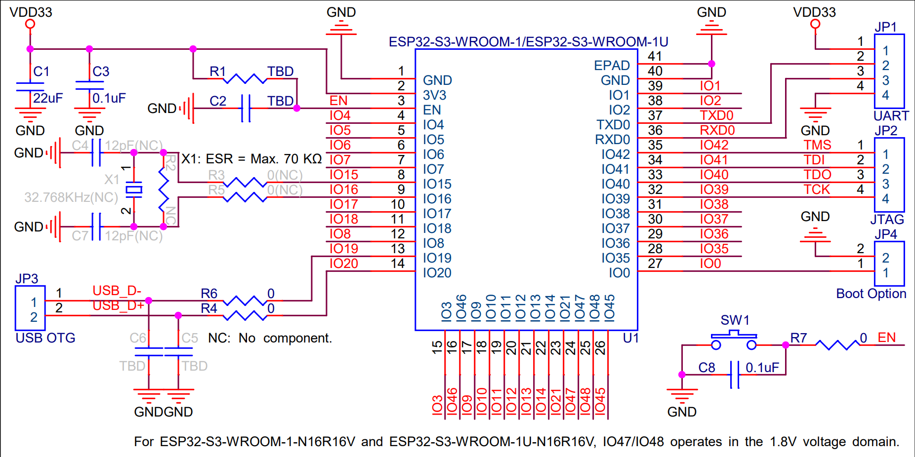
With 600 LEDs, I knew I would not be able to power them using normal USB-C. I considered using a barrel jack and a 5VDC power supply, but it would mean that I would have to find 5V high current power supplies which are not very common. After doing some research, I decided that the best way to power the LEDs would by using a USB-C PD IC to request 20V, and then have a buck converter to bring the voltage back down to 5V with a higher current.
Here are the power calculations I did:
LED power usage: 12mA = 0.012A
600 leds * 0.012A per LED = 7.2A
7.2A * 5V = 36
Based on the calculations, I created a power supply using Texas Instruments Webench Power Designer. I decided to get a buck converter that could take in a voltage range of 19V-20V and output 5V@8A, just to give myself a bit of headroom with power consumption. The designer gave me this power supply schematic. I then copied it into my KiCad design.
Laying out the componants:
With 600 LEDs, I didn’t exactly feel like placing them manually. I did a bit of reaserch and found out that KiCad has a scripting interface that uses python. I have never used the KiCad scripting interface before, and I just wanted to get on with the design, so I used ChatGPT to create a script to place all 600 LEDs and capacitors on the board automatically. After that, I placed the power circuitry on one side along with the USB-C port and placed the footprints for the microcontroller and its supporting circuitry on the opposite side of the board to avoid any potential interference with the power circuitry and the WiFi and Bluetooth on the microcontroller. After that, I used a KiCad plugin called Freerouting to automatically place the traces. While Freerouting did a very good job at connecting the hundreds of LEDs together, it still missed a few connections that I had to fix manually.
After placing the footprints, I ended up with The following design: INSERT DESIGN WITHOUT 3D MODELS
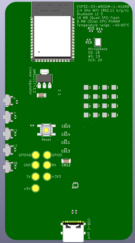
While it does show where all of the footprints and traces are, it is a bit hard to imagine what all of the componants will actually look like. This can be solved in KiCad by assigning 3D models to footprints. This allows you to see a relitivly acurate representation of what the finished PCB will look like. Some of the componants have 3D models built in to KiCad, and if they don’t, it is usually relitivly easy to find 3D models on websites such as EasyEDA. For a few of the components such as the USB-C port I was not able to find an exact match for the 3D model so I had to find something that was close enough.
INSERT DESIGN WITH 3D MODELS
Creating a prototype
I had been working on the design for many weeks now, and it was nearly complete. As it would be very expensive to manufacture, I would need to create a low cost version to make sure the main components would work together. I already knew that the microcontroller, microphone and LEDs should theoretically work together, but I had never tested them. To actually be able to test them, I would have to create a prototype, and I had already created a larger design so I decided to scale it down and create a prototype based on it. 600 LEDs was way to much for a prototype, so I brought it down to just 16 in a 4x4 grid. With only 16 LEDs, that meant I no longer needed the power supply circuitry. This allowed me to make the PCB significantly smaller, reducing its cost. While trying to keep cost down on the prototype, I moved the capacitors for each of the LEDs from the opposite side of the PCB to the same side as it makes it cheaper to manufacture. I decided to keep the microphone as it is a key part of my design as it is very important and it gives me time to fix the design if it does not work. With the desicions that I had made, it would mean I would be testing the following componants:
- Microcontroller
- Logic level shifter (LEDs are dependent on it)
- LEDs
- Microphone

I then sent it off to a PCB manufacturing company in china, specifically JLC PCB. I have used them previously when I designed an NFC buisness card using a PCB and was very happy with the quality and price so I have decided to use them again. The total cost came out to be just over $100USD which is not bad.
Testing the prototype
As soon as I got the prototype, I was exited to get it up and running. I went to plug it in using the USB-C port and shortly realised that I had made a fatal mistake. For a normal USB connection, it needs at least four wires - two for power and two for sending and reciving devices. USB-C has two extra wires that are required to be connected to something according the the USB specification. The two extra wires known as CC1 and CC2 are used to allow devices that need more power (such as a laptop) to request more power. For the prototype, it does not need extra power, so both of the pins are connected to a resistor which is then connected to ground. This tells a charger that the device needs 5V without the device needing a special IC to talk to the charger. When reveiwing the design that I had made, I saw four traces on the PCB going from the USB-C port so I thought it was fine. If you were paying attention, you would have noticed that there should have been six traces going from the USB-C port. I had managed to forget to connect the power pins becuse I saw four wires which is what is normally in a non USB-C USB cable. Thankfully, I was able to fix it by soldering from the port diretly to some test pads that I had added to the PCB.
After fixing the first issue, I thought that would be the end of it - I was wrong. I plugged it in while checking dmesg (a tool which shows lots of useful info including which devies are plugged and unplugged) on my laptop, but didn’t see anything show up. I was a bit confused, so I took a look at the PCB again to make sure that there was no obvious physical issues with it. I then touched one of the LEDs on the board and unplugged it as fast as I could. The LEDs were warm which is never a good thing if they are off. I was rather confused, so I took a look at the schematic and the PCB layout and it seemed fine. I then checked the datasheet and realised what I had done. At some point, I had managed to mix up +5v and GND on the LEDs, meaning that they were shorting the entire board and were now potentially damaged. The data pins on the LEDs were correct unlike the power so I’m not entirely sure how that happened. With the way that I laid out the traces on the PCB I was able to cut the power traces and carefully solder wires to them to fix the polarity issue.
I then plugged in the board again, hoping that it would finally work. I looked at my laptop… and it showed up! I then got started on flashing the WLED firmware to the microcontroller. I have flashed WLED to a few different types of ESP microcontrollers before, and compared to the ESP32 and ESP8266, the ESP32-S3 takes quite a bit more time and knowledge to get it properly funtioning. When flashing it, the ESP32-S3 has a built in USB controller meaning that unlike the ESP32 and ESP8266, does not require a seperate IC to have USB work, and can change what type of device it shows up as to a computer which is why some use it to make keyboards. The disadvantage to this is it disconnects and reconnects from USB every single time that the ESP32-S3 gets reset, which can happen for all sorts of reasons including it having the wrong firmware flashed to it or if it fails to install firmware that gets sent to it. This makes it hard to select in the software used to flash it because it will constantly dissapear. There is a special mode that forces it into firmware flashing mode, which for some reason was not very reliable if an update failed prevously. I eventually managed to get WLED running on it and I started to configure it. I then discovered that I had made a mistake when choosing what pin to use to run the LEDs. The pin I had chosen was not able to correctly run the LEDs. After I added some bodge wires, I managed to get the external led matrix to work.
It was at this point that I got burned out, holidays happened, I was busy, etc.
Part Two:
At the start of 2026, I spent time going over what I needed to work on and fix.
First, the things that I have finished and don’t need to be worried about:
- Using KiCad: Aquiring and using footprints, symbols, and models.
- Manufacturing PCBs: What companies to use, what settings to use, and what parts to select.
- Assembling PCBs: What components to use, what should be placed by the manufacturer, and what I should do myself to keep costs down.
What I need to work on:
- Final PCB Design: I need to finish the large (and hopefully final) PCB, and I need to have lots of test points.
- Figure out why I seem to never be able to get logic level shifters to work.
- Power supply: See below.
Brain Dump for the power supply design:
- It needs 5V at 22A.
- It has to to USB-C PD, but USB-C PD cannot do more than 5V at 3A.
- Current plan is to take 12V from a PD power supply and step it down to 5V.
- Idealy the power supply to convert 12V to 5V will be seperate from the main PCB.
- Should I go with 12V LEDs instead of 5V? 12V power supplies are far more common. Only problem is I would need to find different LEDs.
- For now, I should just design the main PCB such that I can deal with the power supply later.
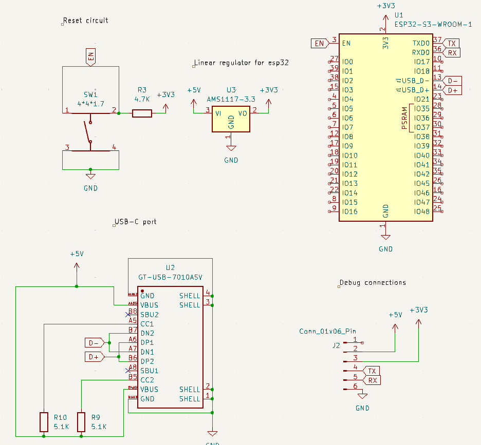
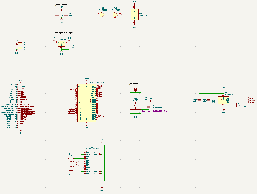
I then started to work on the updated schematic, pulling sections from both of my prototypes. I kept nearly all of the schematic from my 1st prototype for the ESP32, USB-C port, microphone, and power regulation:
As I want to have this finished as fast as possible, I have decided that I will not try to implement USB-C PD on the main PCB, and instead just use a 5V power supply. In order to be able to get power to it, I have added two large pads with a large amount of vias so the pads do not get damaged when I solder to them:
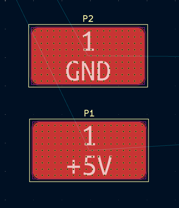
I am also looking at using surface mount screw terminals so I do not have to solder the wires directly to the PCB, which would make it far simpler.
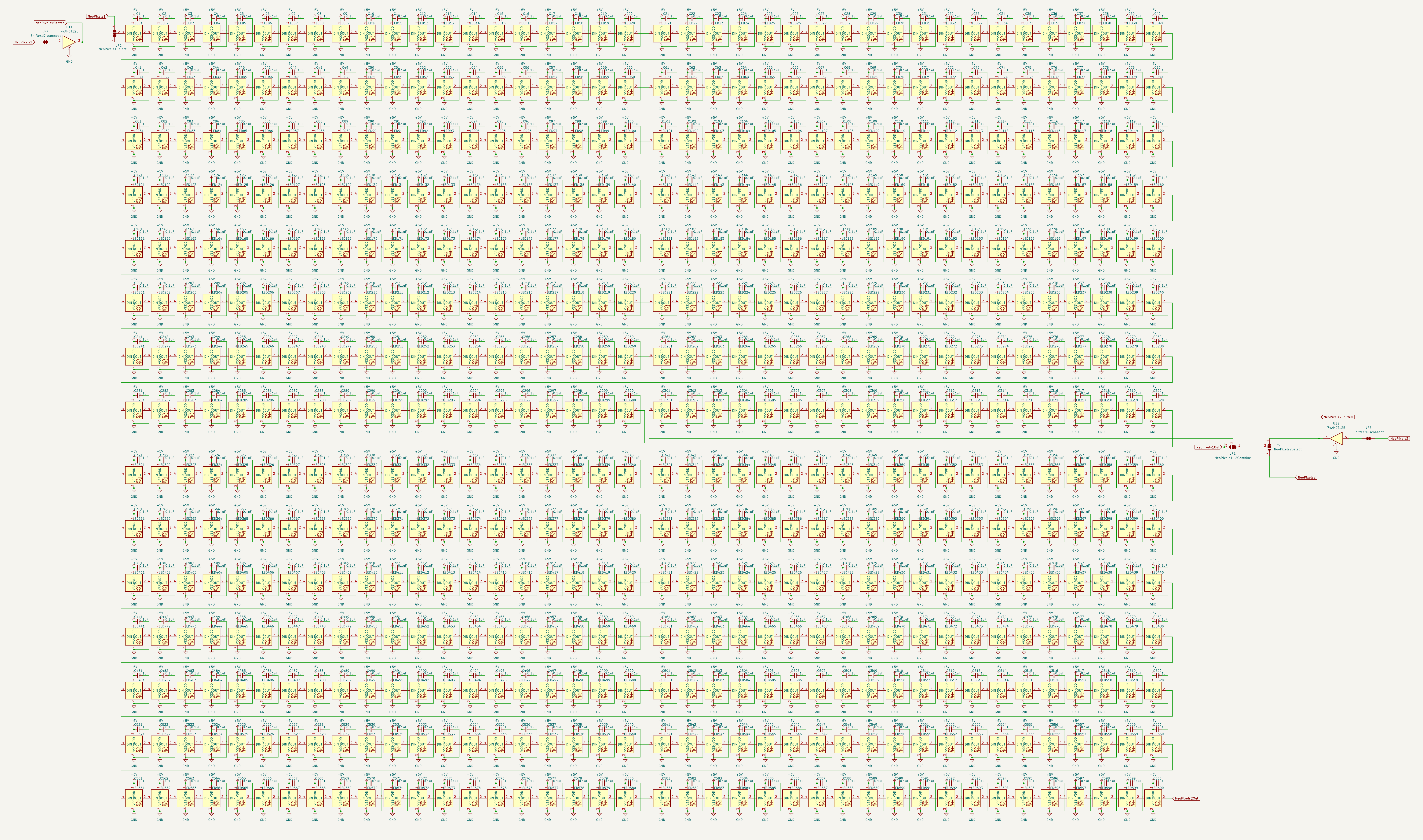
I made the LED matrix far larger, and also updated the LED footprint as it had an error in the last prototype:
After about three weeks, I had put together a mostly complete design, with a few small issues that needed to be solved. The schematic looked like this:
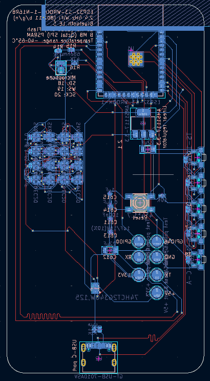
The PCB layout looked like this:
And the 3D model looked like this:
The overall layout is complete, but it is a bit bigger than it could be.
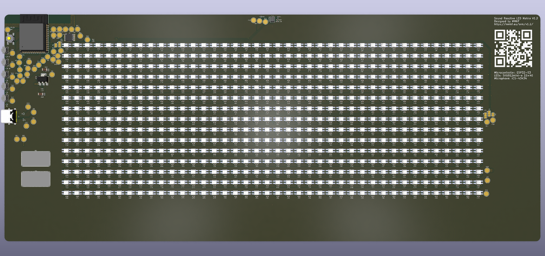
I then added testpoints to all of the unused pins, added a resistor to the output of the output of the level shifter, and fixed DRC errors due to how close the componants are. With everything closer together, some things had to be moved around for it to work. Additionally, I added a qr code and some info on the silkscreen of the PCB.
Final Schematic:
Final PCB:
3D Model of final PCB: